
Help support this website and join AllAdvantage. AllAdvantage places a small banner at the top of your computer screen and in return pay you for surfing the Web. Last month they sent me a check for $78.40. It is a great deal. Click on the link below and check it out.
Project #1
Write Protect the EEPROM of an RCA Model DRD222RD Satellite Receiver
Purpose
To prevent unauthorized intruders from modifying the EEPROM memory of your
receiver.
Warning
This project could permanently damage your receiver. The procedure described
below should be performed by a person experienced in electronic modifications.
Tools
Torx Head screw driver set ( to remove cover).
Good fine tip soldering iron and solder.
Sharp x-acto knife
Drill and drill bits
Materials
30 Gauge wire-wrap wire
SPDT Toggle switch
10k 1/4 watt resistor
0.1uF ceramic capacitor
Step 1
Use Torx head screw driver to remove four screws from rear of unit.
Remove the cover from the unit
Step 2
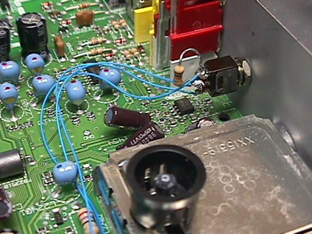
Locate the 24C32 serial EEPROM device at the right and center of the board.
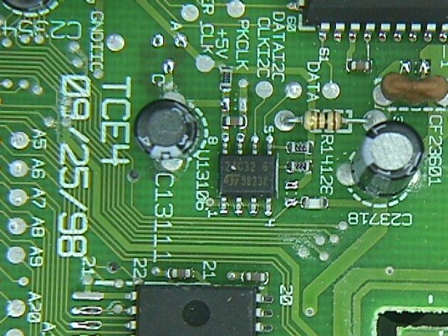
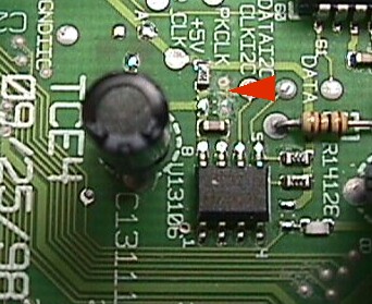
Step 3
With an x-acto knife, cut the trace that connects to pin 7 of the 24C32
device. You may cut near the ground via at the end of the trace as shown below.
Alternatively, you may cut near the IC pad between pin 7 and the chip cap.
Step 4
Solder a piece of wire-wrap wire to the part of the cut trace that still
connects to pin 7 of the 24C32. Make sure the wire is long enough to reach to
the rear of the unit.
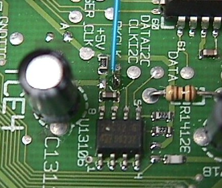
Step 5
Add another wire to the test pad marked +5V. Also add a lead wire to one of the
test point pads marked Gnd. Also, if you chose to cut the trace in the location
shown, add a 0.1uF cap across C13111 as shown.
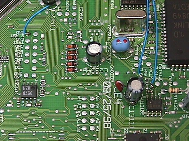
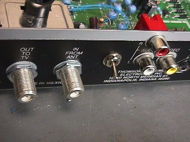
Step 6
Carefully drill a hole in the rear of the receiver. The hole should be of
adequate size to mount the toggle switch.
Step 7
Solder the 3 lead wires to the toggle switch as follows:
|
Signal
|
Pin on switch
|
|
+5 V
|
Top
|
|
Pin 7 of 24C32
|
Middle
|
|
Gnd
|
Bottom
|
Also solder the 10k resistor across the top and middle pin of the switch as shown below.
Step 8
Mount the toggle switch into the rear panel. Replace cover and screws.
Operation
When the switch is in the UP position the EEPROM is in the normal Writeable
state. When the switch is in the down position the EEPROM is in the read only
state. The switch should be left in the down state to prevent any unauthorized
use of the EEPROM device.
FAQ
Q: Does this modification really work?
A: Of course! It works as stated. The mod can be tested by running the
manufacturing test routine. When the switch is in the writeable position
the test will pass. When the switch is in the read only position the test
will fail. Also, user configuration setting won't be store when the switch is in
the read only position. In other words, you can make user configuration
changes to your receiver, but when the unit is powered down all changes will be
lost.
Q: Are you sure this thing works? I think someone is messing with my
receiver!
A: Remember, there is a mirror image of the EEPROM in RAM. If an
unauthorized intruder messes with your receiver, you will have to do a power
down reset to clear the RAM. After the reset, your system should return to the
state it was in before the intrusion. In fact, the receiver shown in these
photos was successfully reset after an attempted "intrusion" earlier
this week.
Q: How does this mod work?
A: The write control line is usually tied to ground to allow writing to
be in the enabled (low) state. We simply added a switch to allow the write
control line to be switch to the disabled (high) state.
Q: Will this modification protect my receiver?
A: It will keep unauthorized intruders from storing information in the
EEPROM. If you are having this type of problem then yes, it should protect your
receiver. Keep in mind that there may be other devices within the receiver
capable of nonvolatile data storage. Time will tell whether or not this
modification will have long term positive benefits.
Q: I have receiver XXXXXX, will this modification procedure work for
me?
A: From what we have seen, pretty much every receiver contains a serial
EEPROM device similar to the 24C32. Therefore, you should be able to locate the
device and perform a modification. Probably the best mod for other types of
receivers would be to heat and lift pin 7 off the board. Then attach the wire
directly to that pin. This is especially true on older through-hole type of
boards since the pin is likely attached to ground on an inner-layer. The switch
and resistor arrangement used in this project should be the same. Also, there
would be no need to add a capacitor with this type of mod.
Q: Can I short some pins on the 24C32 to clear it's memory?
A: OK the jury is still out on this one. In general shorting pins does
not sound like a good idea. We will wait to see if anything comes of this
method!
LINKS
DSS Cracker Website - Need a complete DSS Programming Package? Check out the DSS Cracker Website.
Help support this website and join AllAdvantage. AllAdvantage places a small banner at the top of your computer screen and in return pay you for surfing the Web. Last month they sent me a check for $78.40. It is a great deal. Click on the link below and check it out.